Operation of Conventional Oven Magnetron
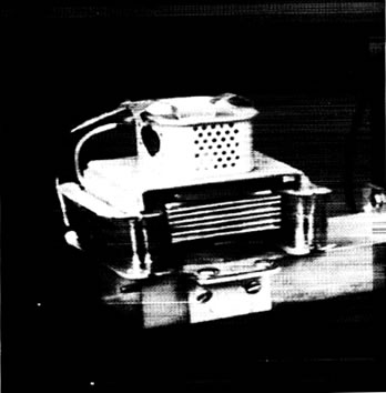
Figure M1. Conventional microwave oven magnetron whose magnetic circuit has been modified by the addition of coils.
A magnetron (shown in Figure M1) is a high power microwave oscillator which can be used to generate microwave power at high frequencies. As shown in Figure M2, a DC voltage is applied between the cathode and the anode. The electrons produced by the heated cathode are accelerated toward the anode due to the DC voltage source E. The strong magnetic field in the region between cathode and anode produces a force which acts on each electron causing the electrons to spiral away from the cathode all with different curvatures, depending on the initial velocity of each electron when they leave the cathode.
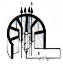
Figure M2. Cavity Magnetron (Anode and Cathode Structure)
A cloud of electrons will therefore be formed at the vicinity of the anode. This cloud falls under the influence of the RF field at the vane tips (capacitor portion of the equivalent resonant circuit as shown in Figure M3), and electrons will either be retarted in velocity or accelerated. Since the force produced by the magnetic field B on each electron is proportional to the electron velocity, the retarted velocity electrons will experience less curling force than the accelerated electrons. This will create a collection of electron spokes (Figure M4), with spoke located at the resonator having an opposing RF field. On the next half cycle of RF oscillation, the RF field with have opposite polarity causing the spoke to rotate in order to maintain its presence in an opposing field.
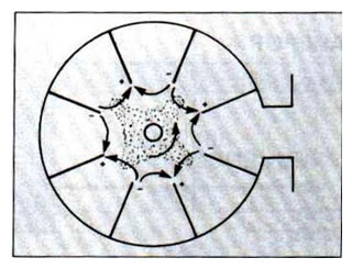
Figure M4. Electron Spokes in Magnetron
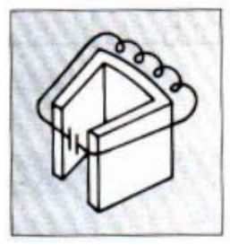
Figure M3. Magnetron Resonator
