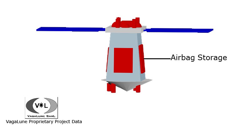
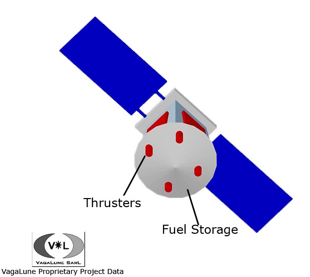
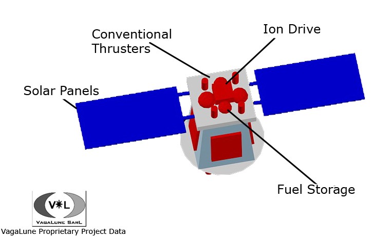
| The designs shown below provide a rough sketch of the Lunar Module (LM) in flight configuration (because the solar panels are shown unfurled). The LM in its compact state (not shown) will fit inside the Falcon 1e fairing. The conventional fuel is stored both in the top (~5 kg) of the LM for flight adjustments and the bulk (~30 kg) is stored in the conical base section. The ion drive is placed in the top of the LM along with the ~80 kg of pressurized Xenon fuel. Mountings for the airbags are placed around the body of the LM module. Pressurized Helium for inflating the airbags upon descent is also stored in the conical base section.
Located inside the LM is the Moon Rover (MR), held in place by struts to prevent shocks and vibrations felt by launch and descent. Communication systems for the LM are stored in the top, and are connected to the MR systems. After landing (and deflation of the airbags), all necessary information is transferred to the MR and then the link between the two modules is broken. The MR then becomes independent and the LM systems are no longer part of the mission. More specific details on the the systems for the LM and MR are here. |