
Lander to Astronaut Link
Propagation Model
For the communication link between the astronaut and the Lander, a sufficient propagation model for the moon was used. The propagation model was obtained from a NASA technical memorandum [2]. The equation for propagation loss (LdB) is shown in equation 2.
LdB |
= 10log10(GTGR) + 20log10(hThR) – 40log10(d) |
(2) |
Where, |
|
|
GT |
= Gain of the transmitter (dBi) |
|
GR |
= Gain of the receiver (dBi) |
|
hT |
= Height of the transmitter (m) |
|
hR |
= Height of the receiver (m) |
|
d |
= Distance of link (m) |
|
Using the loss model in Equation 2, the total link loss for the maximum distance of 2 km was derived. Table 1 shows the total link loss, along with the parameters used for the model.
GT |
GR |
hT |
hR |
d |
LdB |
0 dBi |
0 dBi |
2 m |
5 m |
2 km |
112.04 dB |
Additionally, a correction factor must be added to the loss to account for average fade depth. A number of standard deviations are also added to the loss to provide 67%, 95%, or 99% confidence intervals (CI). From the NASA technical memorandum [2], these factors for 2.4GHz operation and transmission between a Lander and astronaut are shown in Table 2.
Average Fade Depth |
Additional standard deviation |
Total Propagation Loss |
6.38 dB |
(5.26, 10.52, 15.78) dB |
(123.68, 128.94, 134.20) dB |
To ensure proper operation with 99% confidence, 134.20 dB of loss is used for the total propagation loss at 2 km.
Noise Power
Initially, the full bandwidth of the antenna was used to determine the noise power from equation 1. These calculations provided a worst case for the noise power, while maximizing the possible throughput of the link. Table 3 shows the noise power using the full bandwidth of the antenna, as well as the final bandwidth chosen.
PN |
k |
Tsys |
B |
-115.41 dBW |
1.39 x 10⁻²³ JK-1 |
345 K |
600 MHz |
-145.41 dBW |
1.39 x 10⁻²³ JK-1 |
345 K |
0.6 MHz |
The final bandwidth of 0.6 MHz was chosen to minimize noise power while ensuring sufficient throughput (at least 100 kbps) for the communication link.
Transmit Power
Given a noise power of -115.41 dB, using the full bandwidth of the antenna, or -145.41 dB using a lower bandwidth of 0.6 MHz, the total transmit power could be derived assuming a target value for CNR. From Pratt [1], with no error correction coding, a total CNR of 10 dB will accomplish a small bit-error rate (BER) of 10-6 using BPSK modulation. However, with the addition of error correction coding, covered in the Error Correction section below, a smaller value of 5 dB CNR could be used while still achieving a BER of less than 10-6. Table 4 shows the transmit power in order to achieve the target CNRs.
CNR |
Bandwidth |
PT |
10 dB |
600 MHz |
28.79 dBW = 756.8 W |
5 dB |
600 MHz |
23.79 dBW = 239.3 W |
10 dB |
0.6 MHz |
-1.21 dBW = 756.8 mW |
5 dB |
0.6 MHz |
-6.21 dBW = 239.3 mW |
Using error correction coding, and a bandwidth of 0.6 MHz, the total transmit power required has been reduced to 240 mW. In order to ensure full operation, a total transmit power of 250 mW is chosen.
Modulation Scheme
Several tradeoffs exist between different digital modulation schemes. Simple modulation schemes like BPSK require the lowest relative CNR values while achieving a target BER. However, higher order schemes like QPSK provide additional throughput using the same bandwidth. Equation 3 from Pratt [1] shows the symbol rate (Rs) given an occupied RF bandwidth.
Rs |
= Bocc /(1 + α) |
(3) |
Where, |
|
|
Bocc |
= Channel bandwidth |
|
α |
= Filter roll-off factor |
|
With a total possible bandwidth of 600MHz and a roll-off factor of 0.5, a throughput of 400 Msps could be achieved. With simple BPSK modulation, the total throughput is 400 Mbps. This is well above the required throughput of 100 kbps; therefore, a lower bandwidth should be chosen in order to reduce the noise power.
In order to allow low CNR values, BPSK modulation is chosen. Error correction, described in the Error Correction section below, is added to the link, which adds redundancy. We have decided to use 200 kbps as our target bit rate; therefore, with rate ½ error correction doubling the number of bits and using BPSK modulation, an overall bit rate of 400 kbps is needed. Using equation 3, the channel bandwidth required is 0.6 MHz.
Error Correction
Forward error correction allows the receiver to detect and correct errors without retransmission of data. For a target BER value, adding error correction consequently reduces the required CNR value. For battery-powered and long-distance applications, such as our location service on an astronaut, the possibility of low a CNR is important, since this ensures a lower required transmit power for a target maximum distance.
Using BPSK modulation, in order to achieve a low BER of 10-6, a CNR of approximately 10 dB is required in the absence of error correction. Using a rate ½ convolutional code (K = 7), the CNR is reduced to approximately 5 dB given the same probability of bit error. Figure 2 from Pratt [1] shows a simple convolutional encoder.
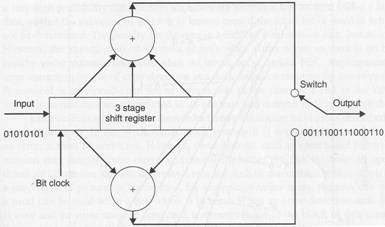
Figure 1: Simple Convolutional Encoder
For our application a rate ½ convolutional code with K = 7 was chosen. With respect to Figure 2, K = 7 would increase the shift register to a total of seven stages. Using this convolutional code, a CNR of only 5 dB is required to achieve a BER of less than 10-6.
References:
[1] T. Pratt, C. Bostian, T. Allnutt, Satellite Communications, 2nd edition, Wiley, 2002.
[2] Larry Foore and Nathan Ida, Path Loss Prediction Over the Lunar Surface Utilizing a Modified Longley-Rice Irregular Terrain Model. NASA Technical