
Antenna
Measurements
For antenna measurements, first the monopole was tested on a network analyzer at Georgia Tech to
confirm efficient operation within the 1-3GHz band. During the S11 measurement on the network analyzer,
small adjustments were made to the vertical element length in order to achieve acceptable S11 values for
the desired frequency. Figure 2 shows the antenna connected to the network analyzer.
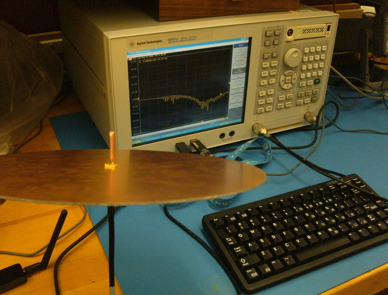
Figure 2: Antenna Measurments with Network Analyzer
The S11 measurement provides the reflection loss, and a smaller value is desirable, as this indicates
an efficient transfer of energy to the antenna (i.e. it is radiating efficiently) [1]. The S11 values
measured for our antenna can be seen in Figure 3.
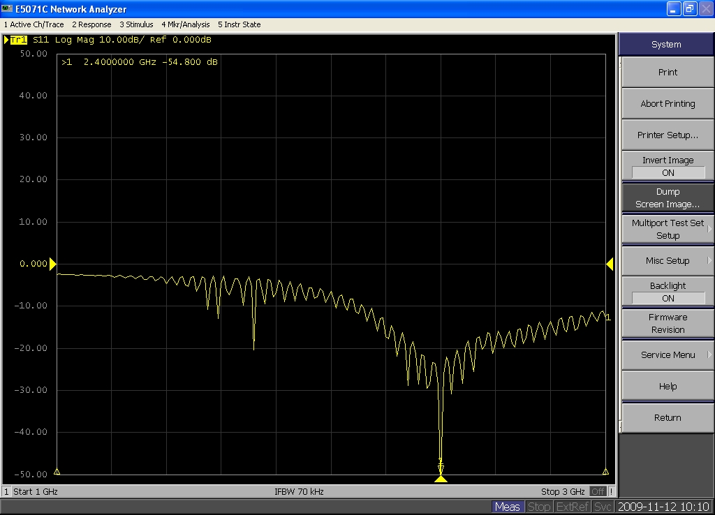
Figure 3: S11 Measurement with Network Analyzer
With a minimum reflection loss of approximately -54dB at 2.40GHz, our antenna should perform well within
the 1-3GHz band.
Next, the antenna was sent to REAL in order to be measured accurately in an anechoic chamber. The test
facility consists of the chamber, a horn antenna, and an antenna mount to mount the experimental antenna.
The facility provides remote control via the Internet in order to obtain measurements. Figure 4 shows
our antenna in the test chamber.
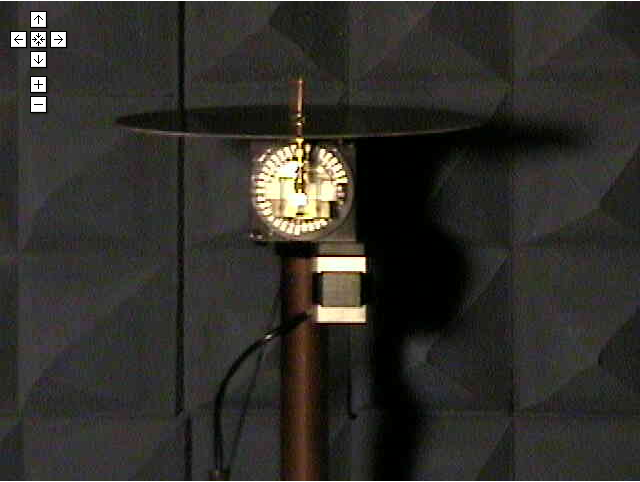
Figure 4: Antenna in REAL Test Chamber
Figures 5, 6, and 7 show the measurements from the test. Figure 5 shows the S11 reflection values and a
minimum is seen at approximately 2.43GHz. Also from the S11 measurement, the bandwidth was determined to
be 600MHz.

Figure 5: S11 Measurement from REAL
The azimuth cut is shown in Figure 6. An optimal polar azimuth cut for an omni-directional antenna would be
a circle, as this ensures equal radiation in all directions along the azimuth plane. From Figure 6, our antenna
operates very well as an omni-directional antenna in the azimuth plane.
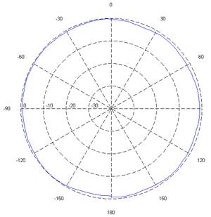
Figure 6: Azimuth Cut from REAL
Figure 7 shows the elevation cut for our antenna. A typical omni-directional elevation cut is
“butterfly-shaped” since it radiates relatively well in all directions except directly
above and below the radiating element. For the most part, our antenna follows this pattern; however,
some inefficiency is noticed around the 150 and -150 degree elevations.

Figure 7: Elevation Cut from REAL
The overall gain for our antenna was taken to be 0dBi. The gain measurement from REAL was
approximately 35dB, which is too high for an omni-directional antenna. It is likely that the
gain from the testing horn antenna should be taken out of the overall gain measurement. We attempted
on several different occasions to contact REAL about the gain measurement, but we never received
a response.
References:
[1] Antenna Starter Kits from REAL, http://www.preal.ece.cmu.edu/resources/manual/AntennaStarterKits.pdf