
The Antenna
For communication between the astronaut and the Lander, a suitable omni-directional antenna was designed. The specifications required RF communication within a 1-3GHz range; therefore, the antenna was designed to meet this requirement. Several different design options were considered, but ultimately, a monopole design was chosen. After construction of the antenna, several preliminary measurements were taken using a network analyzer to verify efficient operation in the 1-3GHz range. Finally, the antenna was sent to the Remote Educational Antenna Lab (REAL) at Carnegie Mellon University for more accurate measurements in an anechoic chamber. Table 1 shows the final measurements for our antenna.
| Operating Frequency | Range | Gain |
| 2.43GHz | 600MHz | 0dBi |
Design
Several design options were considered during the initial design phase. Two antenna designs were seriously considered including a collinear dipole and a monopole antenna. An omni-directional 2.4 GHz collinear antenna could be made simply with a coaxial cable and a connector [1]. A monopole antenna could be made with a 1/4 wavelength vertical element, ground plane, and a connector [2]. The monopole antenna was chosen for its ease of construction and availability of parts.
Monopole Antenna
For the monopole antenna, a 1/4 wavelength 3.97mm diameter copper rod was used along with a 25.4cm
diameter ground plane. The ground plane was obtained from and cut by Bob House in the Georgia Tech
ECE department. The assembled monopole is shown in Figure 1.
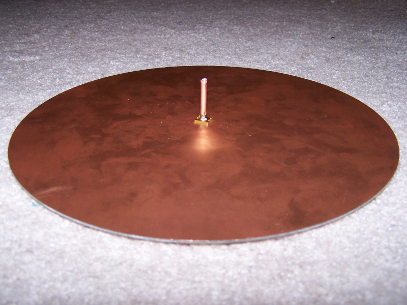
Figure 1: Assembled Monopole Antenna
References:
[1] DIY Colinear Dipole, http://wireless.gumph.org/articles/homemadeomni.html
[2] Monopole Design, http://273k.net/gsm/designing-and-building-a-gsm-antenna/monopole/