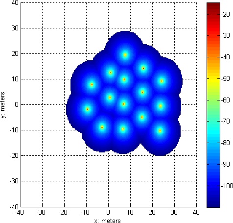
Covering the most area possible near the lander
The astronaut might also want to cover the most area possible near the lander. In this case the RFIDs will look like a spiral.
 |
 |
 |
 |
 |
 |
It is not a coincidence that the elements of the spiral look like a tessellated hexagon because trilateration produces three different loci:
These three loci form a hexagon, so the overall spiral near the lander is really just concentric hexagons.
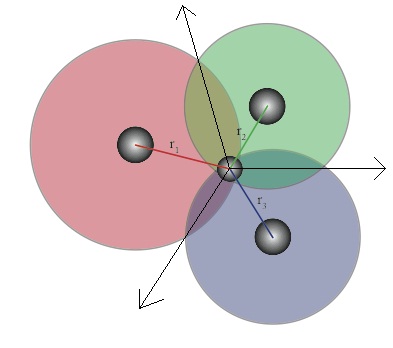
Finally, notice that maximizing the path along the locus means the 2nd, 4th, and 5th RFIDs will always form an equilateral triangle, regardless of how close together the 2nd and 3rd RFIDs are. This natural use of equilateral triangles will minimize the possible error due to angle measurements, making this algorithm more reliable than the straight line algorithm depicted earlier.
The Matlab code for both algorithms