
The RFID System
Our RFID based location tracking system is novel in the sense that we have used two algorithms to handle the way an astronaut would like to move around the Lunar Lander. Our system, like any other common RFID system, consists of Passive tags, a Reader and the Middleware, which is responsible for doing all the location computation. The novelty of our system is the RFID dispenser.
The Dispenser is an automatic RFID tag dispenser. It is interfaced to the reader and based on signal strength and other parameters it drops the appropriate tag at the appropriate location. The following sections describe the details of the Tag, the Reader, the display unit.
The RFID Tag
The tag is a digital passive RFID. We use tags with 16KB of memory and capable of operating at extreme temperatures on the Moon. The 16KB memory is used to store the tag ID (integer) and the write the approximate distance (floating point) from the Lunar Lander to the tag.
The temperatures on the moon vary in the following ranges:
| Mean surface temperature (day) | 107°C |
| Mean surface temperature (night) | -153°C |
| Maximum surface temperature | 123°C |
| Minimum surface temperature | -233°C |
Assuming that the Astronaut is going to be wandering during the day and not during the night it is reasonable to have components that would operate well at about 107°C.
Our tags have a substantially enhanced survival temperature in the range of -40° C to 300° C and an operating temperature range of approximately -20° C. to 200° C. These have a thermal housing at the base and top that forms a chamber. The housing comprises of a first thermally resistant material, which is Polyphenylene sulphide (PPS) compound. Polyphenylene sulphide is known to resist chemicals and high temperatures [1].
The circuit board substrate is placed within the chamber having a second layer of thermally resistant material. This material consists of a pre-conditioned polyimide. Polyimides are known for thermal stability, good chemical resistance, excellent mechanical properties. Polyimides compounded with graphite or glass fiber reinforcements have flexural strengths of up to 50,000 p.s.i. and flexural moduli of 3 million p.s.i. Thermoset polyimides exhibit very low creep and high tensile strength. These properties are maintained during continuous use to temperatures of 450 °F (232 °C) and for short excursions, as high as 900 °F (482 °C). Molded polyimide parts and laminates have very good heat resistance. Normal operating temperatures for such parts and laminates range from cryogenic to those exceeding 500 °F (260 °C) [3].

Figure 1: RFID Tag
The Reader
Our reader is basically a transceiver that is capable of reading and writing onto the RFID. The reader has the following features:- Reads the tag ID and the distance from the Lunar Lander – The distance parameter helps the Astronaut to choose arbitrarily which direction to go on the basis of which tag is closer to the Lander.
- Can predict the approximate direction of the tag.
- Provides a touch sensitive display to show all tags in range.
- Has an automatic Tag Dispenser.
- No special thermal protection needed. It can be integrated with the already well-protected communication system in the space suit.
The Dispenser includes a RFID writer. Using the Astronaut to Lander link the dispenser knows the distance from the Lander to the Astronaut. It programs this onto the tag when it ready to drop a tag. The dispenser also monitors the distance from the previously dropped tag after every ~9 meters. The block diagram of the Reader is shown below [2].

Figure 2: Reader Block Diagram
The processor in the reader is an Atmel AT91SAM7S128 ARM based general purpose microcontroller operating at 55MHz. Typical core supply is 1.8V, I/Os are supplied at 1.8V or 3.3V and are 5V tolerant. An integrated Voltage Regulator permits single supply at 3.3V. The processor is capable of running our location algorithm with reasonable accuracy.
The Display Unit
The Display gives the Astronaut information about which tags are within range and at what distance based on RSSI. Since we program the tags with its approximate distance from the Lander, the readings on the display tells the Astronaut which tag would take him to the Lander faster. The display is also capable of telling the approximate direction of the tag, which helps the Astronaut to move in the right direction.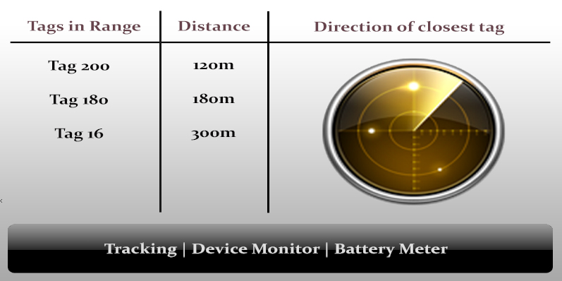
Figure 3: Screenshot of the display
References:
[1] High temperature RFID tag, United States Patent 5973599 Visit
[2] Block Diagram - RFID Reader Visit
[3] Polyimides Visit