Carrier Spacecraft
The carrier is the spacecraft that will transfer our lander from Earth to Venus. Once the carrier has delivered the lander, it is not required anymore.
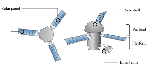
Figure 1 shows the spacecraft configuration for the orbiting phase. The configuration shown does not include the 2nd stage; only the upper stage configuration is shown. There are three solar panels to generate power. The spacecraft has two main subsystems, the payload system and the platform system. Payload includes all entry systems and the lander system. The platform system has a propulsion system, attitude control system, and communication system. In the entry phase, the solar panel and 1 m antenna are separated from the payload system using a separation-impulse device [43]. The separation-impulse device is a very stable technique to produce separation from the main body. This technique is widely used for the separation of a rocket’s fairing.
Weight and power
Table 1 provides the total weight of our system. The propellant weight is estimated based on the analysis of the required propellant described in the propulsion design section. Other values are estimated based on the flagship mission design [1]. The total weight is around 2700 kg. The allowable payload weight of the Atlas 5 is 4000kg. The designed spacecraft satisfies the launch vehicle requirements.
| Subsystem | Components | Weight (kg) |
|---|---|---|
| Lander | GPHS | 137.5 [38] |
| Stirling engine | 34 | |
| Electronics | 15 | |
| Motor | 6 | |
| Antenna | 50 [44] | |
| Structure | 170 | |
| Sensors | 2 | |
| Total lander | 444 | |
| Entry system bus | Attitude control | 1 [1] |
| C&DH | 1 [1] | |
| Power | 1.5 [1] | |
| Inflatable parachute system | 48 [1] | |
| Structure and mechanism | 105 [1] | |
| S/C adapter | 6 [1] | |
| Harness | 14 [1] | |
| Telecom | 0.25 [1] | |
| Thermal | 210 | |
| Margin | 30 | |
| Total entry + lander | ||
| Carrier mass | Attitude control | 30 [1] |
| C&DH | 12 [1] | |
| Power | 31 [1] | |
| Liquid hydrazine | 138 | |
| Structure | 300 | |
| S/C adapter | 13 [1] | |
| Harness | 28 [1] | |
| Antenna | 50 [44] | |
| Thermal | 30 [1] | |
| Margin | 60 | |
| Carrier bus mass | 690 | |
| System contingency | 140 | |
| Hydrazine propellant | 1015 | |
| Total | 2720 | |
| Launch vehicle capability | 4000 |
Communications
The communication requirements are far lower than those for the lander itself, due to the low data rate required. The carrier will use a low gain antenna for the first phase of the voyage, and a high gain dish antenna for the cruise itself. The transmitted data consists of the spacecraft state and health monitoring. A data rate of 160 bits/s is expected [28]. The corresponding RF bandwidth is then 7.5kHz. For the noise power calculation, we followed the same method as for the lander to Earth link. Below is the link budget for the cruise phase of the mission.
| Transmitted Power | 13 dBW (20W) |
|---|---|
| Circuit Losses | -1.5 dB |
| Transmit Antenna Gain | 26 dB (1m diameter) |
| Pointing Loss | -3 dB |
| EIRP | dBW |
| Free Space Loss | -268 dB (2.55e11m, see here) |
| Rain attenuation | -1 dB |
| Receiving Antenna Gain | 54.5 dB |
| Received Power | -180 dBW |
| Noise Power | -184 dBW (54K temperature, 7.5kHz) |
| Received SNR | 4 dB |
| Margin | 3 dB |
During the first part of the voyage, a low gain antenna (7dBi [28]) with 60° beamwidth will be used. Indeed, proper orientation of the high gain antenna is not possible during launch phase.
Propellant selection
In this section, the study for selecting propellant and the feasibility study for Atlas 5 describes. Table 3 shows ΔV analysis results. The required ΔV for Earth to Venus is estimated from the analysis of the optimal trajectory from the Earth to Venus. The delta V for orbit insertion is calculated from the defining elliptical orbit in orbiting phase. The required delta V of orbit trim maneuver is determined from the table 5. Our perigee is 300Km. From the table 4, the required ΔV is 7 m/s per year. In here, our mission is 1 years. Hence, the required ΔV is 7 m/s. The other required delta V is assumed based on the flagship mission [1].
| Phase | ΔV | m/s | Stage | Reference |
|---|---|---|---|---|
| Launch phase | Earth to Venus | 90.06 | 1st stage | |
| Orbiting phase | Orbit insertion | 2846.88 | 2nd stage | see here |
| Gravity loss | 85.5 | Upper stage | [1] | |
| Fuel recovery | 20 | Upper stage | [1] | |
| Orbit trim maneuver | 7 | Upper stage | [1] | |
| Landing phase | Walk-in | 20 | Upper stage | [1] |
| Main phase | 100 | Upper stage | [1] | |
| Walk-out | 27 | Upper stage | [1] | |
| Margin | 50 | Upper stage | ||
| Total | 3246.44 |
| Orbital altitude | Maintenance ΔV |
|---|---|
| 200km | ~130m/s per year |
| 220km | ~37.5m/s per year |
| 230km | 21m/s per year |
| 250km | 7m/s per year |
The launch vehicle (Atlas 551) is selected based on the orbit analysis and the estimate's payload weight. In this section, the feasibility of the selected launch vehicle is investigated. The propellant of the Atlas 551 is HTPB which is a solid rocket. The analysis of the first stage is skipped because the specification of the solid rocket is too hard to get. We performed the analysis for the second stage. In orbit insertion phase, the required impulse Isp to estimate the feasibility of the second stage can be obtain from rocket equation as follows
ΔV = Isp g0 ln(m0/mf)
Where, ISP is a specific impulse, m0 is the initial mass and mf is the dry mass. g0 is Venus gravity. The mass fraction of the initial mass and the dry mass is assumed around 1.6 from the flagship Venus mission.[1] The delta V is 2936.94 m/s. Thus, the specific impulse is 704 sec from the rocket equation. In the case of Centaur 3 in Atlas 5, the type of propellant is Liquid Oxygen and Liquid Hydrogen Storage (LOX/LH2). The Isp of LOX/LH2 is 450.5 sec. The centaur has double engines so, the Isp of Centaur 3 is 901s. This Isp satisfy the required specific impulse for orbit insertion.
Next, we have investigated on the required Isp for orbiting phase. To determine a type of the propellant, the information of specific impulse is a main design factor. The specific impulse can be calculated from the rocket equation. It is assumed that the weight fraction of the initial mass and the dry mass is 1.16 from the weight fraction of Venus flagship lander. [1] From this assumption, Isp is 160 sec. Table 5 represents theoretical performance of liquid rocket propellant combinations. The liquid hydrogen is more attractive. The first reason is that it is widely utilized for the small attitude and trajectory control for the control of satellites. In the orbiting phase, the role of the propulsion is to maintain the orbit and make a thrust for the entry mission. Therefore, the liquid hydrogen is better option. Beside, this propellant has very good chemical characteristics. In other words, it is reliable [40]. For these reasons, the liquid hydrogen is selected for an orbiting mission. The oxygen oxidizer is chosen because it is the safest and the cheapest, as well as the most commonly utilized for in-space states. However, the liquid fluorine is toxic and difficult to handle it. Likewise, red fuming nitric acid is also toxic and hard to control it. Consequently, the oxygen oxidizer and liquid hydrogen are defined for compensating gravity loss, fuel recovery and orbit trim maneuver in orbiting phase.

Carrier Block Diagram
