Payload
This section discusses the payload contained in our Venus lander. The primary goal of our mission is to gather seismic data, so our main focus is on the seismology of Venus and the seismometer we will use. The payload also includes temperature sensors, pressure sensors, an anemometer, and an accelerometer.
Seismology on Venus
The goal of this document is not to discuss the geology on the Venus planet. However, reviewing some basic concepts will help us understand the parameters of interest for choosing our seismometer.
The study of seismic events on a planet can be used to infer knowledge on its internal structure, for instance, thickness of the crust - which in turn, can give us invormation about volcanism - and also state (solid or liquid) of the core. Figure 3 shows, as an example, the ray paths resulting from a seismic event at point 0. The propagation of the seismic waves is constrained by the velocities in the different parts of the planet. Figure 4 gives the corresponding wave velocities.


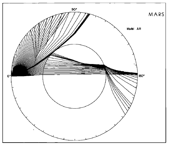

There are two main types of seismic waves: primary (P) and shear (S), with different speeds and modes of propagation (figures 3&4).
Seismic events are usually rare. During the Viking 2 mission on Mars, for instance, only one seismic event was recorded during the first 146 sols (martian days) of the mission [2]. Thus, the 90 days period of consideration for the current Venus mission really is on the lower bound side. To maximize the chance to detect an event, we intent to land several sensors, at different places on the surface, in order to maximize the chances to reach a region of higher seismic activity. Another advantage in having a network of sensors is that the data recorded will be much more useful for understanding the internal structure of the planet than a single sensor. Finally, multiple sensors also reduce the risk of mission failure.
Seismometer design
A seismic sensor is basically a 3-axis position sensor. We can also measure speed or acceleration. Seismic waves usually have frequencies between one tenth of a milliHertz to fifty Hertz. When designing a seismic sensor, one of the main characteristics to take into account is the sensitivity. Indeed, a sensor should detect the smallest signal possible, without being affected by noise. In the case of a Venus seismometer, the sources of noise aren't many, but are important though. Indeed, the winds on the venusian surface can reach 1 meter per second. Thus, we must rule out the effects of the wind hitting directly the sensor from the signal due to ground movement.
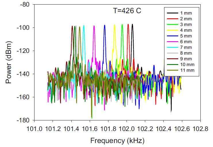
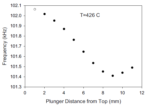
The basic operation of a seismometer is very simple: A mass is suspended by a spring (a leaf spring in our case [5]). When a vibration occurs, the mass is displaced in response. We then need to sense this displacement. The displacement sensing is done by a ferrite core moving inside a coil. Depending on the position of the ferrite core, the inductance of the coil varies, which modifies in turn the oscillating frequency of an oscillator [6, 7]. We then need demodulate the resulting FM signal to retrieve the original signal, ie a voltage proportional to the displacement of the mass. State of the art seismometry uses a feedback loop to keep the mass motionless. This, however, is not ideal in Venus environment.
The proposed design has a sensitivity of 10-9m.s-2.Hz-1/2
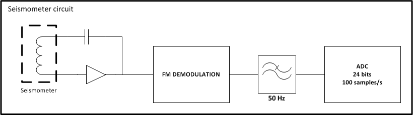
The signal would be filtered at 50Hz frequency and, accounting for a rolloff factor, sampled at 120 Hz.
Temperature sensor
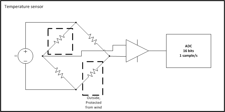
Since the frequency of the oscillator is dependent on the temperature, our payload will also include two temperature sensors: one for the outside temperature, and one for the temperature of electronics. We plan to use a resistance thermometer [29] arranged in a Wheatstone bridge.
Pressure sensor
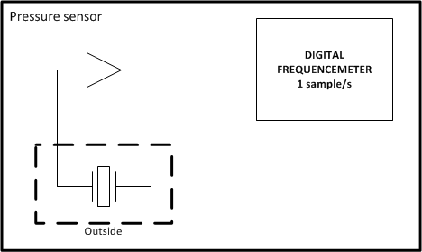
Similarly, pressure will also have to be monitored, to account for it in the seismometer device. We propose using a quartz oscillator, whose frequency will vary with pressure [18]. The actual resolution between frequency shift due to temperature and pressure will be done back to Earth, with the data coming from the temperature and pressure sensors. The signal from the oscillator would directly be digitized, with a reciprocal counter for instance.
Anemometer
Also, an anemometer will be required to distinguish between windburst-induced vibrations and actual quakes [2]. We propose using an acoustic anemometer, like used on the venera 13 and 14 missions [16]. As a side-effect, this microphone-like sensor might be able to detect lightnings, increasing the scientific return of the mission [1], but this wasn't investigated further in this report.. The anemometer might require onboard processing to convert the audio signal into a wind velocity data, in order to save communication bandwidth. Ideally, further investigation would be needed to see whether the sonic anemometer solution is better than hot-wire anemometer...
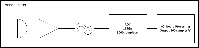
The rolloff requirements are less severe than for the seismometer...
Accelerometer
Finally, we will need a 3-axis accelerometer to measure the tilt of the lander, in order to account for it in the resolution of the 3 axis of the seismometer to the true vertical, N-S and E-W seismic directions. Indeed, it is not guaranteed that the lander will reach perfectly flat ground. At this stage of the study, we plan to operate the accelerometer only right after landing. The accelerometer could be a low power MEMS device, which would take up negligible space and consume only 6 mW [19].
Although using a MEMS accelerometer as the primary way to detect sismic waves could seem legit, those devices generally have a relatively low sensitivity compared to dedicated devices (100 times worse [20]). That's why it would be used only for tilt measurement.