The lander must be kept at a reasonable temperature during operation for proper functionality. The environment of Venus is very harsh, and one problem is the surface temperature. The surface temperature of Venus is approximately 735K, or roughly 460°C. Most electronics only operate around 30° C, and even high temperature electronics operate at 300°C. A two stage Stirling System will be used to cool the lander, seen in Figure 1.
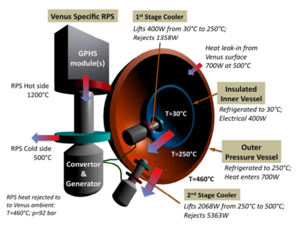
Figure 1 provides a visual representation of the Stirling System that will be used. The first part is the Venus Specific RPS. For this mission, general purpose heat sources (GPHS) will be used (covered more in the power section) to create a temperature difference with the surface temperature. This temperature difference is then converted and sent to the generator to become the power source of the cooling systems. The GPHS modules, converter, and generator need to be outside of the insulation of the lander so that the temperature difference can be properly used for power generation.
The first stage of cooling, the inner cooler, is the cooler that keeps the inner part of the lander around 30°C. It will remove around 400 W of heat from the electronics, which was estimated to be around 375 W. The inner cooler will also remove and heat that has leaked in from the second stage, which is in contact with the outside temperature [1].
The second stage of cooling, the outer cooler, will be in between the inner part with the electronics and the outside of the lander. This section is cooled to about 250°C, this is so the inner part has a somewhat higher temperature to remove the heat to. The outer cooler can remove 2068 W of heat from the outer part. The outer part will see the most heat from the environment, as 700 W of heat will be absorbed by the lander from the environment due to the temperature difference [1].
Silicon Carbide (SiC) will be used as the outer shell. Due to the thermal conductivity of SiC, insulators with very low thermal conductivity must be used to keep as much heat out as possible. A porous silica material, like Zircal, exhibits a thermal conductivity of 0.09 W.m-1.K-1 at temperatures of 400°C [37].
High temperature electronics
Most of our electronics will be kept inside the shell, and thus will be chosen as standard space grade components. However, some of the active electronic circuitry needs to be located very near the sensors for the best noise performance. For those components, we plan on using silicon carbide technology for the MESFETs and aluminium oxide for the packaging[48].
